Contents | About | Contact
article 18, issue 06
Foundation building with human power: ground screws
Theo Schmidt
December 21, 2009 (last update 7.11.2012, new links 2.10.2025)
Abstract
Foundation
laying usually means much back-breaking digging even for small
buildings. Ground screws are a much easier method for supporting
lightweight buildings and are very suitable for installation with human
power. They are also easily removed and reused without using machinery.
Historically called screw piles, they enabled the rapid construction of
foundations for piers and bridges entirely by human power. They were
popular for nearly a century and then somewhat forgotten until
recently, reappearing for modern uses such as foundations for
photovoltaic arrays.
[Editors'
note: While we do cover stationary human power uses in HPeJ, this
rather static application may seem "off-topic". It is however a good
method for securing bicycle sheds and the like.]
INTRODUCTION
Foundations
for buildings or utilities are often made of poured concrete, sometimes reinforced with steel.
While these can be readily built using human power, there are
disadvantages:
- The production of the cement used in the concrete uses a great deal of energy.
- Considerable earth removal and preparation of concrete is normally required.
- When no longer required, the foundation is not easily removed or reused by human power.
There are alternative types of foundations which are especially suitable for construction using human power:
- Earth or ground screws (this article)
These are especially light and can be transported, implemented and reused entirely by human power. - Drystone construction (a future article)
Although
heavy, drystone constructions can be made of stones which are easily
transported, implemented and reused entirely by human power.
Ground screws
Ground screws are a relatively recent development combining properties of pile foundations and earth anchors.
Traditional
piles are generally used as deep foundations, e.g. the many vertical
oak piles the city of Venice is built on. They can support both by
transferring surface loads down to solid ground and by friction along
the whole length of the pile. Piles are often rammed in or vibrated out
using heavy machinery. Smaller piles can be rammed into the ground by
human power with large or special hammers. They can often be removed
with human power using winches.
Earth anchors are steel rods or wire
with helical or expanding anchors at the end or at several places along
the length. The former are screwed into the earth using machinery, the
latter can be rammed in by human power but are generally not
recoverable except by digging or breaking out. They are meant only for
tension loads, which can be in any chosen direction including
vertically upwards, unlike surface anchors or spikes which must be
loaded in a single, mostly horizontal direction.
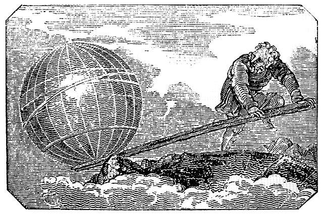
Figure 1: Archimedes: "Give me a place to
stand on and I will move the Earth."
Ground screws
may be loaded in compression, tension, and shear. While they may be
installed using machinery, even large sizes can be screwed in with
human power. As already recognized by Archimedes: "Give me a place to
stand on and I will move the Earth." A great advantage is that they can
also normally be screwed out again by human power - and reused
elsewhere: a semi-mobile foundation. The screwing action also allows
adjusting the vertical depth to millimeter-precision.
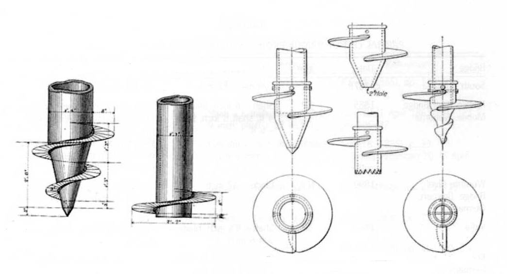
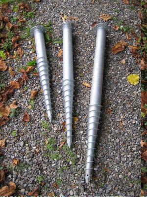 | 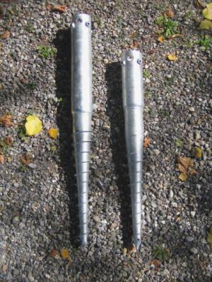 |
Figure 2: Earthscrews with flange (length of thread 0.5 m,
total lengths 0.8, 1.0 and 1.2 m, diameter of tube 75 mm)
|
Figure 3: Earthscrews (length of thread 0.4 and 0.5 m,
total lengths 0.8 and 1.0 m) |
Several types and many sizes exist. I used three each for
supporting a garden house, the flanged ones at the rear and the tubular
ones at the front. I bought various sizes, unsure whether I might hit
large rocks, but in the end was able to use the long ones everywhere.
All six were screwed right in. The front three received extentions in
the form of further steel tubes.
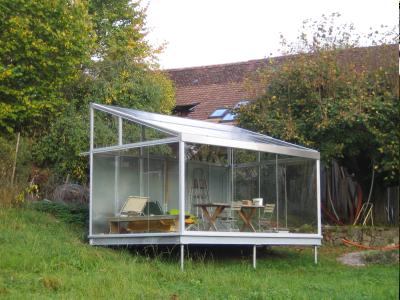
Figure 4: Garden house with 2.2 kW photovoltaic roof, total weight about one tonne
Inserting the earth screws is very easy. They screw with
little effort into the top soil. A spirit level is used to keep the
angle vertical. A short lever is sufficient intially.
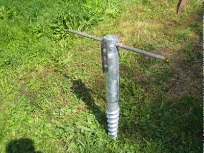 | 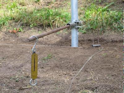 |
Figure 5: Earthscrew being inserted. Note magnetic spirit level. |
Figure 6: Earthscrew nearly in. Note spring scale and water level (plastic tube). |
Our
soil is relatively "ordinary", a farm pasture with topsoil/grass, then
compact soil resting on a layer of conglomerate, frequent rocks and
some clay. After a few turns the thread begins to bite and the torque
rises quickly. A magnetic spirit level is used to keep the screw
vertical. This is easy as long as both arms can be used with a
symetrical lever. Soon a longer lever is required and unless two people
are available, torque on a single lever produces a force which tends to
misalign the screw vertically. If the lever can be easily transferred
to the other side, it is however possible to apply force such that the
misalignment is immediately corrected. Careful attention to the spirit
level allows a near perfect vertical angle and a lateral precision to
better than ± 5 mm. The vertical position can be very precise
simply by stopping at exactly the right position. Multiple screws can
be be brought to the same height with a long spirit levels, a plastic
tube filled with water, or a laser-level.
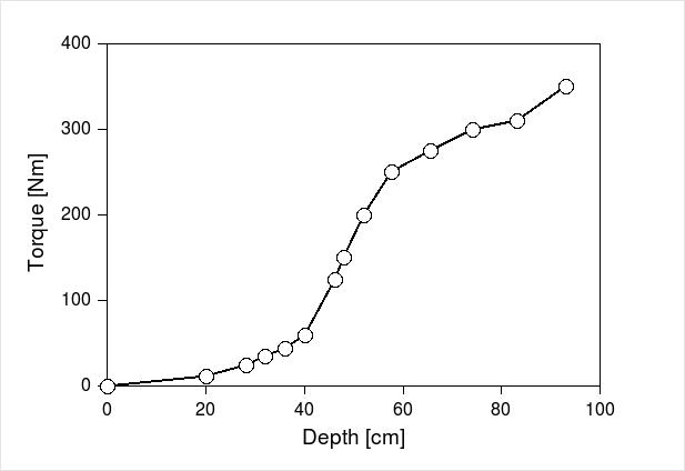
Figure 7: Torque versus depth. The last peak could be a rock,
some of the screws didn't go over 300 Nm.
Support Capacity
The obtainable loading is of course dependent
on the type of soil and on the length of the ground screw. The
following table gives some values when ground screws of similar type as
in the article are subjected to increasing vertical loads and these
measured when the screws have settled 5 mm and 10 mm.Table 3: Vertical loads at 5 and 10 mm settlement, several soil types and several screw lengths, from (Schulz 2004), Table A8-4
Ground
| Clay
| Clay | Clay | Sand, loose | Sand, dense | Gravel, loose | Gravel, loose | Gravel, loose | Gravel, dense |
Length
| 75 mm | 100 mm | 150 mm | 100 mm | 100 mm | 80 mm | 100 mm | 150 mm | 100 mm |
Settlement
| Load
| Load | Load | Load | Load | Load | Load | Load | Load |
| [mm] | [kN] | [kN] | [kN] | [kN] | [kN] | [kN] | [kN] | [kN] | [kN] |
| 5,0 | 6.1 | 34.0 | 84.0 | 15.0 | 19.5 | 3.3 | 6.2 | 9.6 | 51.0 |
| 10,0 | 8.1 | 42.0 | 100.0 | 18.8 | 28.0 | 4.1 | 7.9 | 11.6 | 87.0 |
Historical Development
[All information in this section from Lutenegger (2011), also the figures in the Public Domain]
Ground screws, or screw-piles as they were then known, were first
developed by Irishman Alexander Mitchell from 1833. The first devices
were used for mooring ships and loaded only in an upward direction. The
screw's thread had little more than a single turn and was screwed into
the sea-ground with a temporary shaft later removed.Figure 8: Several forms of screw-piles
Later
the shaft became the foundation pile itself and these were used as the
foundations of offshore lighthouses. One of the first, the Maplin Sands
lighthouse was mounted on nine such iron piles, each about 13 cm
diameter and with a screw flange of about 1.35 m diameter. Each screw
pile was screwed into the sea ground with eight capstan-like levers of
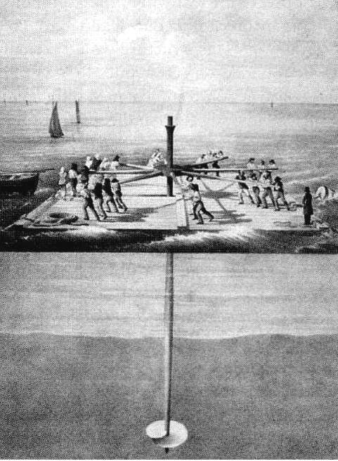
3-5 m length. Figure 9 shows such an arrangement worked by 32 men. Over
60 lighthouse foundations were built in this or a similar manner in
Great Britain and USA.
Figure 9: Capstan on plattform built on two barges, worked by 32 men.
Later
screw-piles were used for pier and bridge foundations. The barge method
of installation prived impractical in a seaway and methods were devised
to work from land, installing the first screw-piles, building and
extending the structure and working from this as it grew. An endless
rope was attached to the capstan and this pulled by men and later
animals or machines. Dozens of screw-pile piers and bridges were built,
some of them famous constructions still in use today.
The
screw-pile technology was in use and known well into the 20th century.
Then it was forgotten for a while until some years ago German Klaus
Krinner developed the form shown at the beginning of this article.
These are now used for all sorts of lightweight constructions such as
fences and photovoltaic arrays, but also buildings.
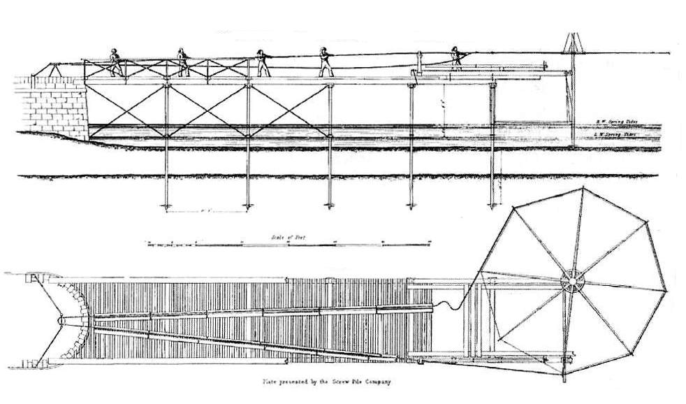
Figure 10: Method for extending pier from land, installing screw-piles with capstan worked by endless rope.
REFERENCES
Contents | About | Contact
Human Power eJournal